Intel released Pentium II and Pentium III processors on the Single Edge Contact Cartridge – or SECC. This type of package was required because it allowed to move the level 2 cache chips from the motherboard closer the to silicone die. Intel wasn’t able to integrate the L2 cache into the CPU die yet. Later Pentium III models, also known as Coppermine, integrated 256kb of level 2 cache on the die.
The original Pentium II (codenamed Klamath) required a core voltage of 2.8 volts. Later Deschutes models, lowered the voltage requirements to 2.0 volts. Early Pentium III models (codenamed Katmai), still required 2.0 volts. Only the later Coppermine Pentium III CPUs reduced the core voltage to 1.75 volts and lower. Intel gradually shrunk the manufacturing process: 350nm (Klamath) to 250nm (Deschutes & Katmai) to 180nm (Coppermine). With smaller manufacturing nodes, voltage requirements drop and frequencies rise.
Unfortunately, if you bought a Slot 1 motherboard for a Pentium II Klamath CPU, chances are that the board does not have a voltage regulator that supports voltages lower than 2 volts. If you are lucky, you will get Katmai Pentium III CPUs to work. An example is the ASUS P2B in revision 2.04. It supports a wide range of CPUs, but can only deliver voltages down to 1.8 volts. Therefore, Coppermine CPUs will not post on this board – unless you’re not afraid to modify the board. The video below show how to replace the power control chip on the P2B to achieve voltages down to 1.3 volts.
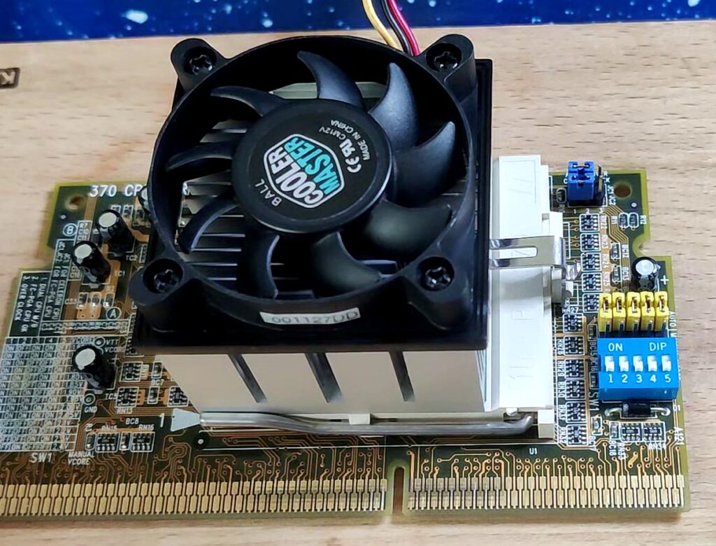
Of course, there are ways to overvolt Coppermine CPUs for Socket 370 from 1.75 volts 1.8 volts. However, you need a suitable adapter. The picture below shows one of those adapters.

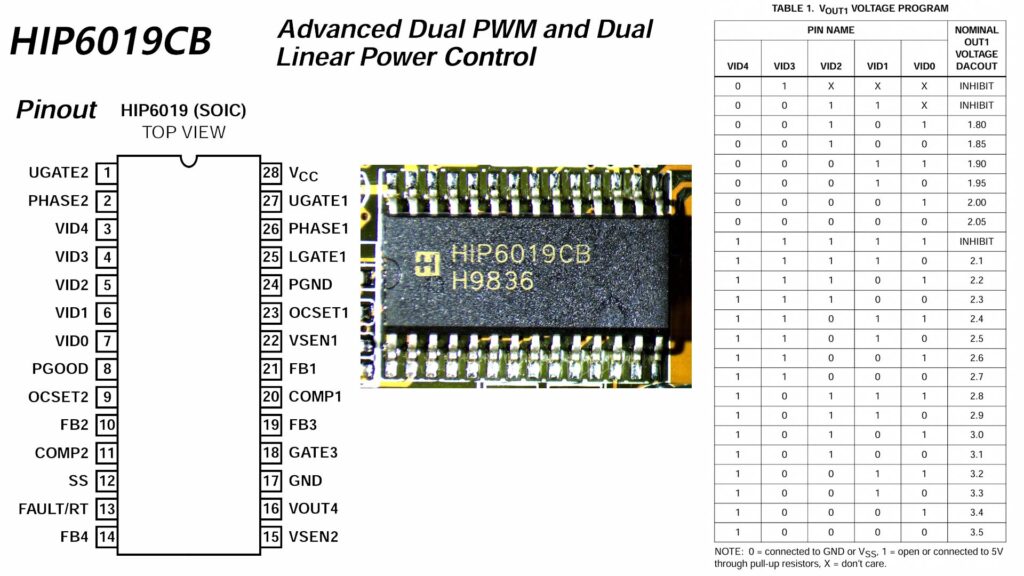
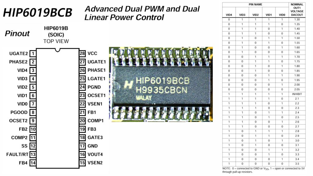
If you have a full-blown Slot 1 CPU, then you are out of luck because there are no DIP switches that allow you to overwrite the voltage requirements of your processor. Luckily, there is a way to modify certain SECC CPUs if you are not afraid to use a soldering iron. The SECC cartridge has 121 connector pins on each side (A and B). Pins A119 to A121, B119 and B120 configure the power control chip on the motherboard. Combinations of 0-ohm resistors allow to configure any voltage required for Pentium II and Pentium III CPUs – provided you have the correct power control chip on the board. Below are two power control chips which are compatible with the ASUS P2B motherboard. The first chip (HIP6019CB) is the original chip. It allows voltages down to 1.8 volts. The second chip (HIP6019BCB) is a drop-in replacement, which allows voltages down to 1.3 volts. You can order the replacement chips from AliExpress for a reasonable price.
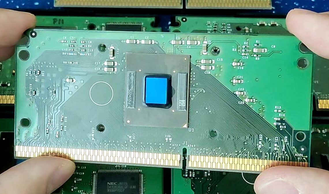
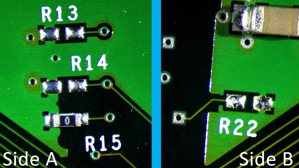
Those “Advanced Dual PWM and Dual Linear Power Control” chips are configured by the Slot 1 CPU. The five pins, A119, A120, A121, B119, and B120 are responsible to send an encoded message in form of the respective pin being connected to Ground or not. Below is a picture of a Pentium III Coppermine 1000 MHz – with a voltage configuration of 1.7 volts. A121 is permanently connected to Ground via a trace. The other four pins are configurable through resistor pads R13, R14, R15 (side A), and R22 (side B).
If you do not want to go through the hassle of measuring which pin on the SECC connects to which resistor pad and controls which VID pin on the power control chip, then you can use the following Excel sheet which can tell you what resistors need to be set for a given voltage – or you can enter what resistors are present, and it will tell you what voltage the cartridge will request from the motherboard VRM.
For more information, please have a look at the video below:
One interesting experiment would be to find out the same resistor set that Genesys modified on their B-52 MMX CPUs, based on Deschutes Pentium II chips (SL2W8 I think they were.). Kinda like how the Slot A Athlon can be resistor modded in the absence of a Goldfinger device. (I have conducted such an experiment with a 600MHz Athlon on Pluto core, which currently runs stable at 800MHz. An entire 200MHz boost!)