
This is the reference companion to my video on building AirMeter – an open-source wireless mod that taps directly into the multiplexed LCD glass of a DTM0660-based multimeter and streams the live reading to a web dashboard, OBS overlay, or anywhere else, with access to UART and no proprietary apps, Bluetooth or locked WiFi protocols.
The video covers the full reasoning and reverse-engineering process. This post is the one to keep open while you actually build it: parts, wiring, configuration, and assembly, step by step. Full source, Gerbers, and firmware are on GitHub – this guide follows that repo closely, so you can cross-reference at any point.
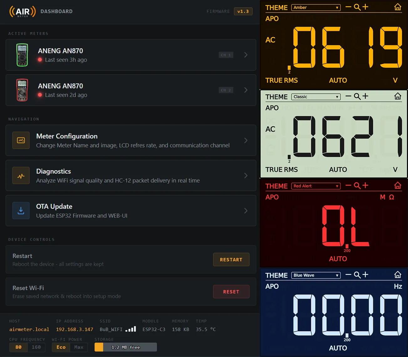
How It Works
[LCD glass] --19 multiplexed lines--> [Comparator PCB] --clean digital levels--> [RP2040 Zero]
                                                                                        |
                                                                                  decodes + frames
                                                                                        |
                                                                                   [HC-12 TX]
                                                                                        |
                                                                                     ==radio==
                                                                                        |
                                                                                   [HC-12 RX]
                                                                                        |
                                                                              [ESP32-C3 SuperMini]
                                                                                        |
                                                                          Wi-Fi + Server-Sent Events
                                                                                        |
                                                                              [Web dashboard / OBS]
The short version: the display driver (a DTM0660, sealed under an epoxy blob) never got wired out to a usable UART pin on this meter – patching the EEPROM to enable serial output doesn’t help if the silicon was never bonded to that external pad in the first place. So instead of chasing a data line, AirMeter reads the 19 raw traces that drive the LCD glass itself, converts that multiplexed analog signal into clean digital data with a small comparator board, and reconstructs the exact screen state in real time.
If you want the full “how I figured this out” story – probing the glass with a scope, mapping all 60 segments by hand – that’s in the video. This guide picks up from “here’s what to build.”
Compatibility
| Hardware | Requirement |
|---|---|
| Multimeter | Any meter using the DTM0660 driver in its 4 COM × 15 SEG (19-line) multiplexed configuration. Confirmed on the ANENG AN870. Most important is how the DTM0660 looks on your multimeter PCB because you need to attach the custom PCB to that chip somehow. |
| ESP32-C3 SuperMini | ⚠️ Check the main chip’s laser etching starts with FH4P4 (e.g. FH4P4M4470). This confirms embedded flash, 105°C rating, 4MB flash, and QFN32 package – modules with a different marking (e.g. starting with N instead of H) are only rated to 85°C and may not be reliable for this build. |
The repo's roadmap includes extending support to other DTM0660-based meters. If you're adapting this to a different model, verify your unit's segment map first using the probing method described below — don't assume it matches without checking.
Parts List
| Part | Role | Qty | Link |
|---|---|---|---|
| RP2040 Zero | Samples the comparator outputs, decodes the display, frames data for the radio | 1 | https://s.click.aliexpress.com/e/_c3gPgH9d https://s.click.aliexpress.com/e/_c4LTiAtZ |
| ESP32-C3 SuperMini (FH4P4 chip – see Compatibility above) | Receiver – Wi-Fi, web dashboard, SSE | 1 | https://s.click.aliexpress.com/e/_c3KVwqfH https://s.click.aliexpress.com/e/_c3dDKQZZ |
| HC-12 433MHz wireless module | Radio link between meter and receiver | 2 | https://s.click.aliexpress.com/e/_c2uYvTPp |
| 3.3V boost converter | Regulated power for the comparator/radio side | 1 | https://s.click.aliexpress.com/e/_c2vdVEuJ https://s.click.aliexpress.com/e/_c4rXT7gj |
| Custom comparator PCB | See BOM below – fabricated via PCBWay | 1 | https://www.pcbway.com/project/shareproject/AirMeter_Wireless_Multimeter_1e73f069.html |
| Arduino Uno (or any AVR board) | Temporary – only used to configure the HC-12 modules. You probably can also use the ESP32 or RP2040 – just adapt the sketch | 1 | you probably already own one – OR – Adapt the code for ESP32 / RP2040 |
| ANENG AN870 | The multimeter I used to develop AirMeter | https://s.click.aliexpress.com/e/_c3Up6jiX https://s.click.aliexpress.com/e/_c2x7xVpV | |
| ZOYI ZT219 | Identical to ANENG AN870 | https://s.click.aliexpress.com/e/_c37jbpIP https://s.click.aliexpress.com/e/_c4loFfZN |
Comparator PCB – Bill of Materials
The comparator board is what turns the LCD’s alternating multiplexed voltages into clean logic levels the RP2040 can actually read. It’s built around five quad comparators:
| Component | Designators | Package | Qty | Value |
|---|---|---|---|---|
| Comparator | U1–U5 | TSSOP-14 | 5 | LM339LVPWR [LINK] |
| Capacitor | C2, C4–C12, C14, C18 | C0603 | 12 | 100nF [Kit LINK] |
| Capacitor | C1, C3, C13, C15 | C0603 | 4 | 2.2µF [Kit LINK] |
| Capacitor | C17 | C0805 | 1 | 10µF [LINK] [LINK] |
| Capacitor | C16 | C1206 | 1 | 22µF [LINK] [LINK] |
| Ferrite Bead | FB1 | L0805 | 1 | 100Ω @ 100MHz [LINK] |
| Resistor | R1 | R0603 | 1 | ~270kΩ¹ [Kit LINK] |
| Resistor | R2 | R0603 | 1 | ~1MΩ¹ [Kit LINK] |
| Resistor | R3 | R0603 | 1 | ~1MΩ² [Kit LINK] |
| Resistor | R4 | R0603 | 1 | ~180kΩ² [Kit LINK] |
¹ Voltage divider off 3.3V, targeting ~2.3 – 2.7V – the “is this line at 3V?” threshold. ² Voltage divider off 3.3V, targeting ~0.3 – 0.7V – the “is this line at 0V?” threshold.
You can use an online voltage divider calculator to find other resistor values that would still satisfy the requirements. If you get the kit, you can substitute 270kΩ with 300kΩ and 180kΩ with 200kΩ. The values given in the BOM are the best possible values to get to 2.5V and 0.5V – there is a generous margin you can substitute values!
Full Gerbers and this BOM as a CSV are in the repo under PCB/.
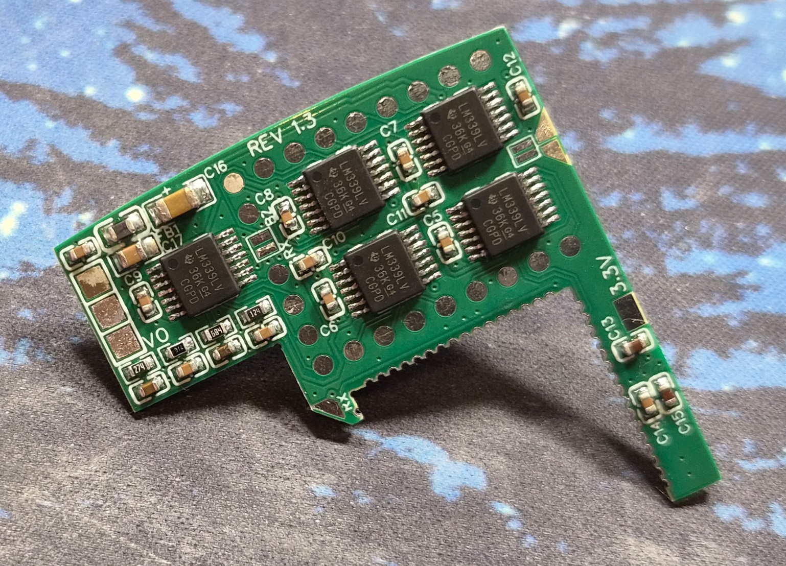
Why the Comparators Are Necessary
You don’t need this section to complete the build, but it explains why the board isn’t a simple pass-through.
Each of the 19 LCD lines doesn’t sit at a stable logic level – the driver constantly alternates polarity to avoid degrading the liquid crystal with DC bias, so any single line looks like a busy staircase on a scope: 0V, 1V, 2V, 3V, repeating roughly every 2ms. A segment is lit whenever there’s a full 3V differential between its COM and SEG line, but that 3V can appear as either COM:3V / SEG:0V or the inverted COM:0V / SEG:3V depending on the current polarity cycle.
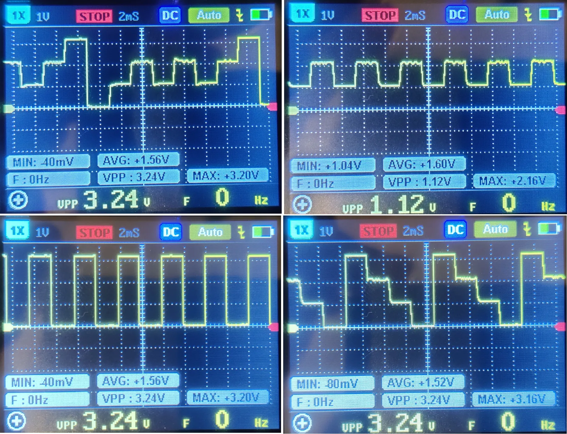
The comparator board’s job is to turn that analog staircase into a clean digital 1 or 0 the RP2040 can sample on a GPIO: one voltage divider sets a ~2.5V threshold (“is this line at 3V right now?”), a second sets a ~0.5V threshold (“is this line at 0V right now?”), and the LM339 comparators output a clean logic level against those references. Five quad comparators (20 channels) comfortably cover the 19 signal lines.
Wiring
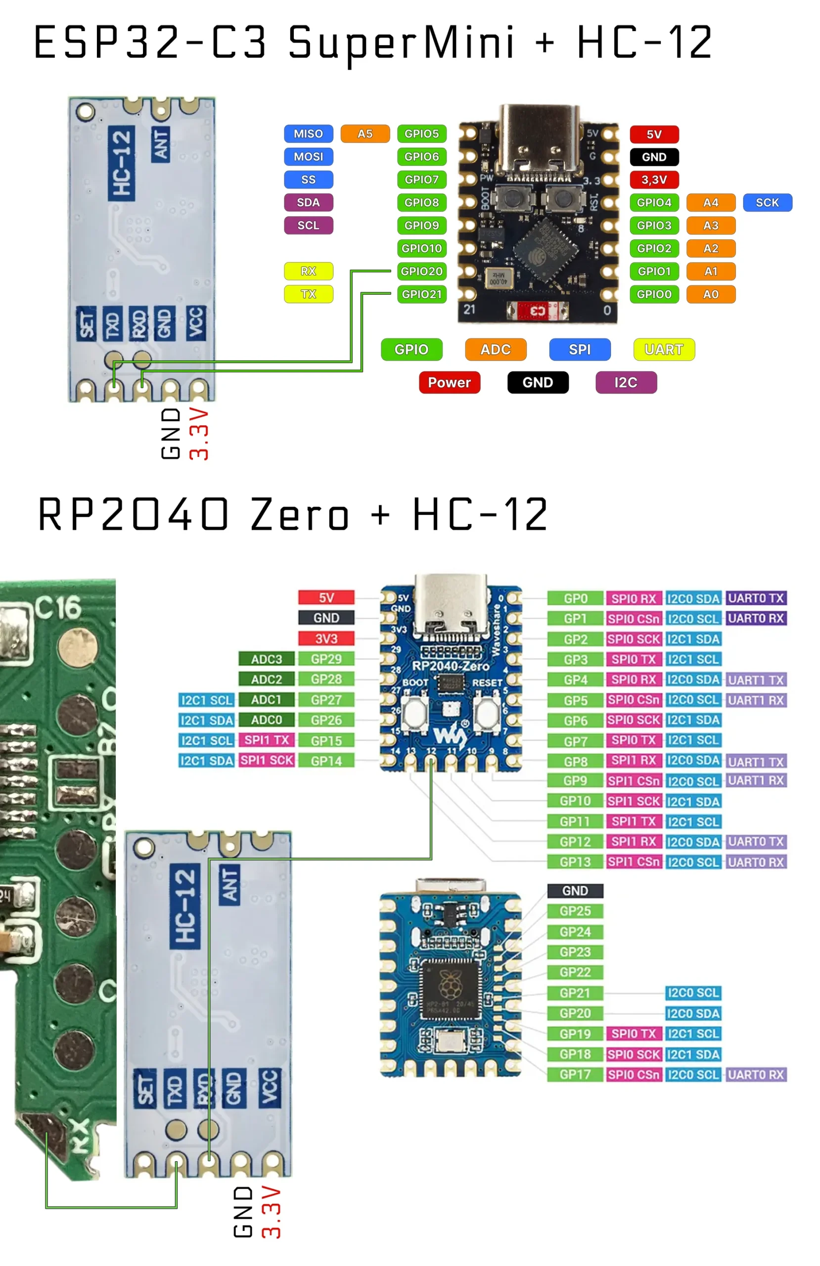
Exact pin assignments are defined in the firmware source (RP2040_Zero.ino and ESP32_C3_SuperMini.ino in the repo) – use those as the source of truth if anything here and the diagrams disagree.
Golden rule for the radio link, on both ends: TX always connects to RX, never TX to TX. Whichever pin on the HC-12 sends data goes to a listening (RX) pin on the microcontroller, and vice versa. Double-check this before soldering – the HC-12’s pads are small enough that re-flowing a wire after final assembly is a genuine hassle.
Configuring the HC-12 Radios
Both HC-12 modules need to agree on the same radio settings before they’ll talk to each other, and the defaults they ship with aren’t appropriate to just leave as-is. AirMeter uses:
| Parameter | Value | AT Command | Why |
|---|---|---|---|
| Baud Rate | 9600 bps | AT+B9600 | Standard transmission speed |
| Channel | C003 (434.6 MHz) | AT+C003 | Operating frequency |
| Transmit Power | P3 (+5 dBm) | AT+P3 | Medium-low power – plenty for desk range |
| Working Mode | FU1 | AT+FU1 | Low-power mode, ~3.6mA idle current |
The easiest way to apply this: wire one HC-12 at a time to an Arduino Uno and run the Arduino_UNO_HT-12.ino sketch from the repo – it sends the AT commands above and can verify a bidirectional link between both modules before you commit to soldering either one in. Do this on the bench, before final assembly – the modules are far easier to reach now than after they’re mounted.
Flashing the Firmware
RP2040 Zero – native UF2 drag-and-drop, no IDE required:
- Download
AirMeter_RP2040_Zero.uf2from the repo’s Releases. - Hold the BOOT button, plug the board in via USB.
- Drag the
.uf2file onto theRPI-RP2drive that appears. - It flashes and reboots automatically.
ESP32-C3 SuperMini – two options:
- One-click, browser-based flashing (Chrome, Edge, or Opera – Web Serial isn’t supported in Safari/Firefox): plug in the board and use the online installer linked in the repo.
- Or flash manually via Arduino IDE – if you go this route, you’ll also need the LittleFS upload plugin to push the web UI files in
ESP32_C3_SuperMini/data/onto the board’s flash.
Assembly
Safety first: disconnect any test probes and remove the battery before opening the meter or soldering anything inside it.
- Build the comparator PCB – order the board and parts per the BOM above, solder the five LM339s and supporting passives.
- Verify your segment map (skip if you’re on a stock AN870) – confirm your unit’s COM/SEG layout matches the repo’s segment map before wiring further; cheap meters can share a glass design across firmware variants, but it’s worth a quick check.
- Wire the comparator PCB to the RP2040 Zero – don’t forget the Pins 17 and 20 which go to dedicated pads on the custom PCB.
- Pre-configure the HC-12 pair on the bench, as above – do this before final assembly.
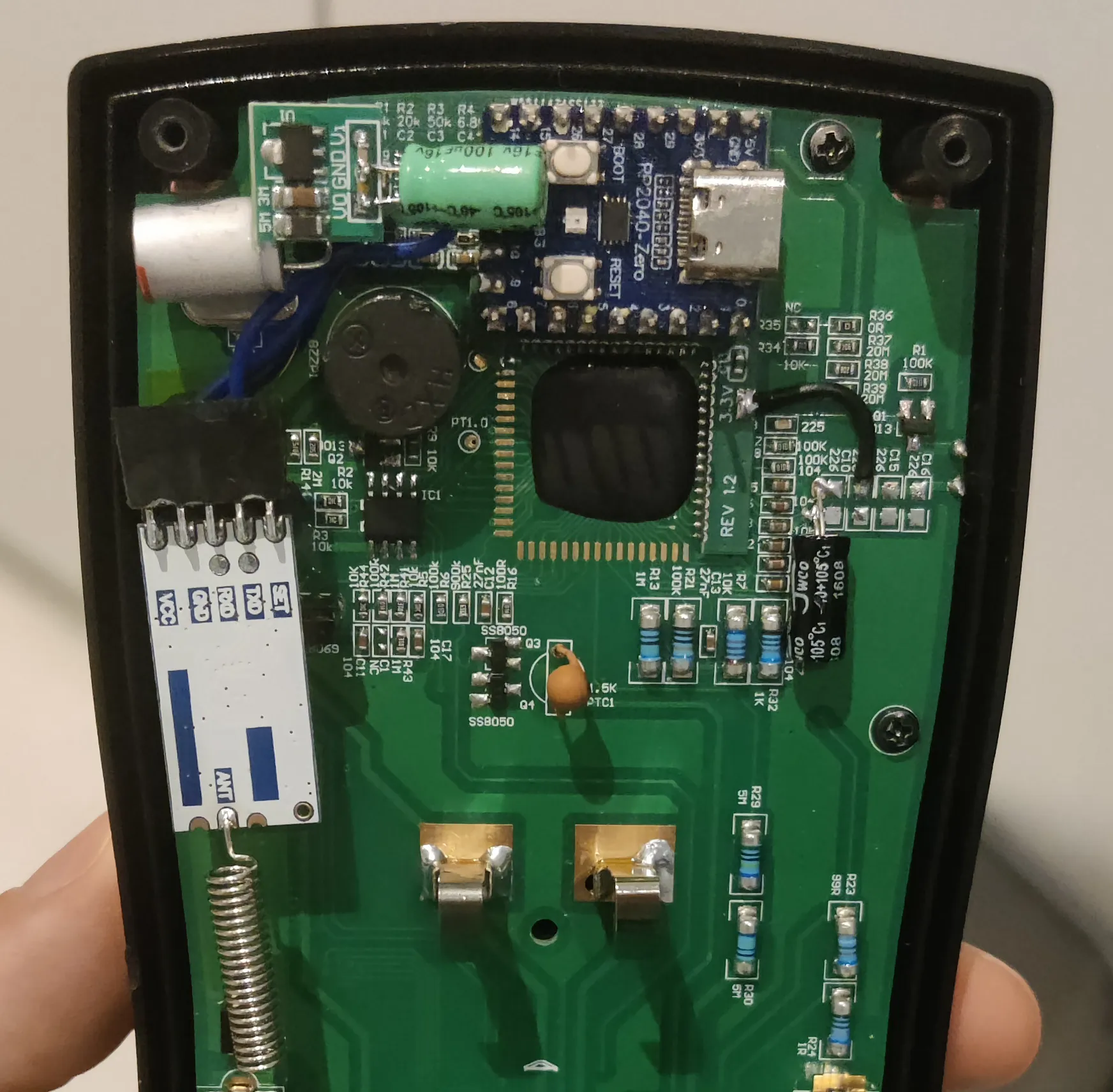
- Assemble the transmitter side: comparator PCB, RP2040, HC-12, and the 3.3V boost converter, all powered from 2× AA cells, mounted inside the multimeter enclosure. Dry-fit everything and confirm the case/cover still closes before soldering anything permanently.
- Flash the receiver ESP32-C3 and upload the web UI to LittleFS. Recommended: use the one-click flasher from the GitHub repository, which handles both.
- Power up the receiver and connect to its
AirMeter-SetupWi-Fi access point (passwordairmeter123), then use the setup wizard to join your home network. - Open the dashboard at
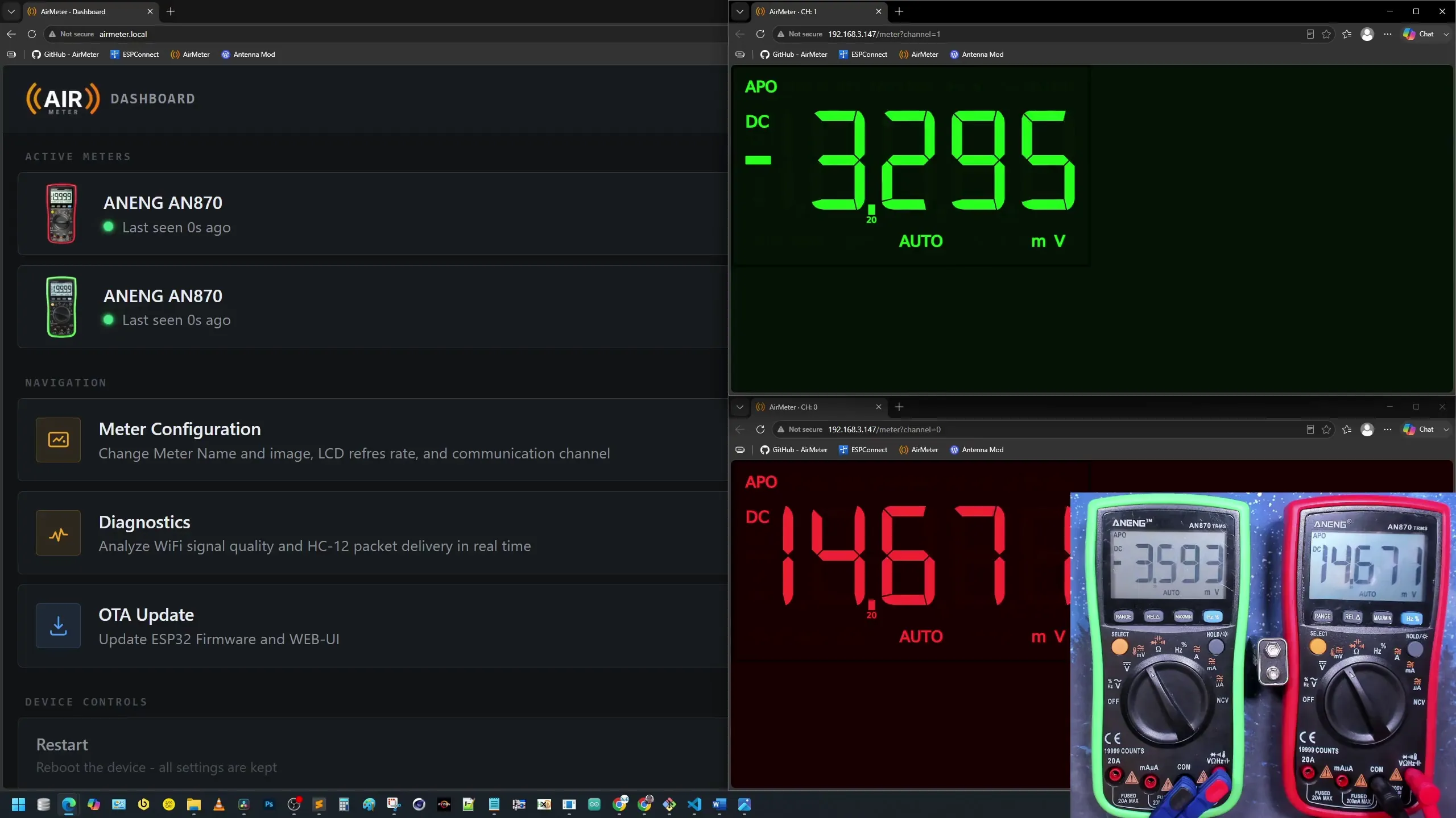
airmeter.local(or the IP your router assigned). The meter auto-registers the first time a packet arrives on its channel.
Using It
- Per-meter settings – name, face image, radio channel, refresh rate – are all configurable from
meterConfig.htmlon the dashboard. - Live view (
meter.html) ships with a dozen-plus built-in themes (Classic, Amber, Red Alert, Neon Cyan, Glass Dark/Bright, and more), adjustable zoom, and persists your settings per meter – drop it straight into OBS as a Browser Source (I use a browser source width: 1000px and height: 1440px). - Multiple meters can run simultaneously, each auto-assigned its own channel on the dashboard. HOWEVER, with more devices chatting on the same channel, data collision will appear. The more meters talk, the worse the the connection for all. I didn’t test it, but I think you can’t run many more meters in parallel than 2.
Troubleshooting
| Symptom | Likely cause |
|---|---|
| No data reaching the dashboard | TX/RX swapped on an HC-12 pair – check both ends |
| Readings garbled or segments flicker incorrectly | Comparator threshold resistors off-spec, or HC-12 channel mismatch between the pair |
| ESP32-C3 won’t hold the web UI / LittleFS upload fails | Check your module’s chip marking – non-FH4P4 variants may lack the flash needed for firmware + UI together |
| Weak wireless range | Confirm both HC-12s are on matching Channel/Power/Mode settings; check antenna orientation – maybe have a look at the antenna mod. |
| Cover won’t close | Recheck component placement and wire routing on the transmitter side before final assembly |
Resources
- GitHub repo – Gerbers, BOM, firmware, segment map, HC-12 sketch, full write-up: github.com/BitsUndBolts/airmeter
- One-click ESP32 flasher: bitsundbolts.github.io/airmeter
- Full build video the reasoning and reverse-engineering behind this guide
AirMeter is open source under the MIT license. If it saved you a weekend of reverse-engineering, the project has a YouTube channel, Buy Me A Coffee, and Patreon if you’d like to support future builds.