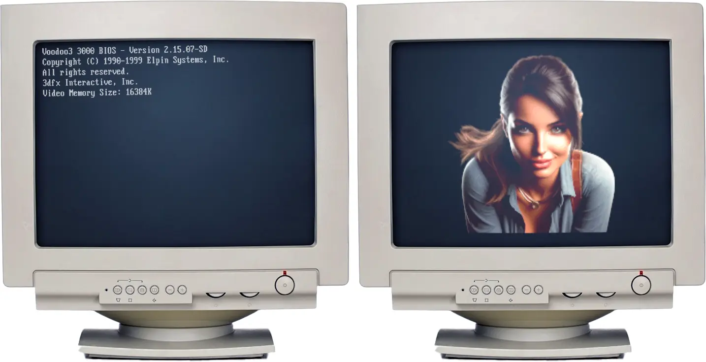
We’ve all seen the classic text splash screens on vintage VGA cards – showing the model, BIOS version, and memory count. But what if we could replace that boring text with a full-color, 256-color image?
Recently, while working with an S3 Trio 3D, I noticed something interesting about the BIOS chips. This discovery sent me down a rabbit hole involving Hex editors, Ghidra, and assembly opcodes. Today, I’m going to show you how I doubled the BIOS size of an S3 ViRGE and injected a custom splash screen.
The Discovery: Finding “Free” Space
It all started when I read the BIOS of a Trio 3D using NSSI. While the BIOS code itself was only 32KB, the chip it was stored on – an HT27C512 EPROM – was actually a 64KB chip.
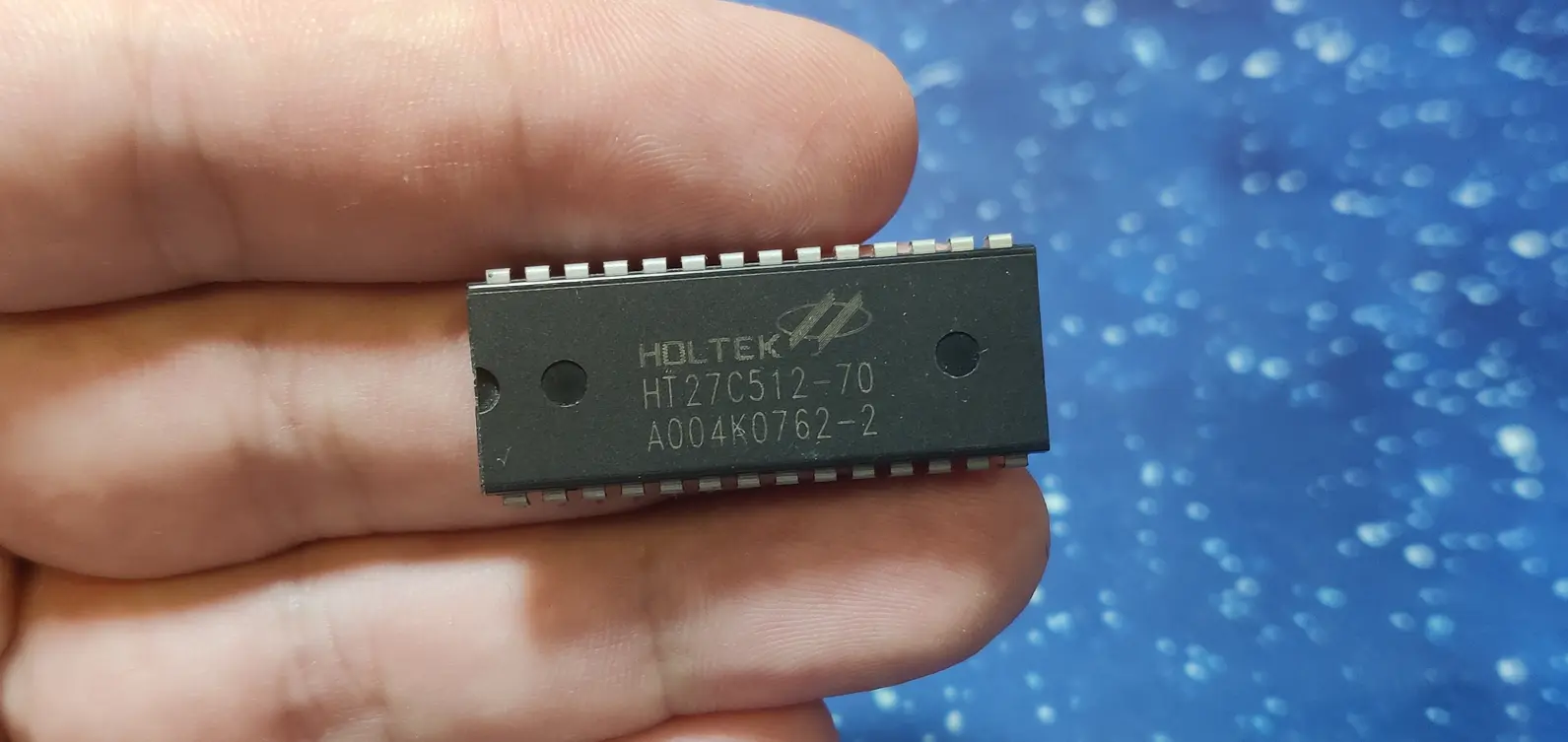
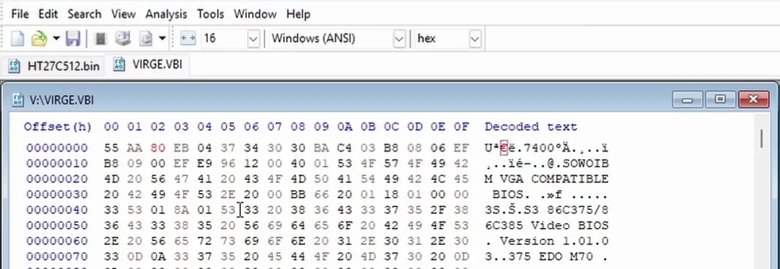
Looking at the S3 ViRGE BIOS, it also defaults to 32KB. However, by changing the “size indicator” byte (the third byte in the file) from 40 (32KB) to 80 (64KB) and moving the checksum to the very end of the 64KB range, I successfully tricked the card into recognizing the extra space.
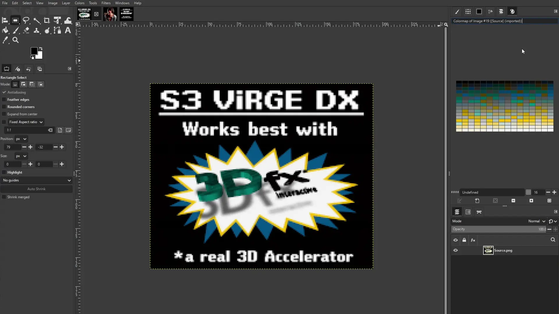
Phase 1: Preparing the Pixels (GIMP)
You can’t just drop a JPEG onto a BIOS chip. We have limited space (32KB of extra room) and specific hardware requirements.
- Resolution: I found 192 x 160 worked best. (Note: You’ll need to squish it vertically in GIMP to account for the aspect ratio shift during boot).
- Indexing: The image must be converted to Indexed mode (256 colors).
- The Palette Hack: This is the tricky part. The ViRGE’s RAMDAC uses 6-bit color values, but GIMP exports 8-bit values. I developed a PAL to VGA Palette Converter to divide every value by 4.
Phase 2: Mapping the Memory
With our image data and palette ready, we need a plan for where they will sit in the new 32KB block (starting at address 8000).
- 8000 – 8100: Custom Assembly Code (The logic to display the image).
- 8100 – 8400: The 256-color Palette (768 bytes).
- 8400 – FC00: The Raw Image Data.
Here is the code that starts from 8000h. In the video, I use a slightly different code that leaves the image splash screen longer on the screen.
60 1E 0E 1F FC B8 13 00 CD 10 BA C8 03 32 C0 EE
42 BE 00 81 B9 00 03 F3 6E B8 00 A0 8E C0 B8 40
C8 8E D8 BE 00 00 BF 40 19 BB A0 00 BA DA 03 EC
A8 08 74 FB EC A8 08 75 FB B9 C0 00 F3 A4 81 C7
80 00 4B 75 E7 B8 00 86 B9 0F 00 BA 40 42 CD 15
B8 03 00 CD 10 1F 61 E8 A9 C7 C3
If you do want the same code I used in the video, replace:B8 00 86 B9 0F 00 BA 40 42 CD 15
with B8 00 86 B9 4C 00 BA 4B 00 CD 15
Phase 3: The Ghidra Surgery
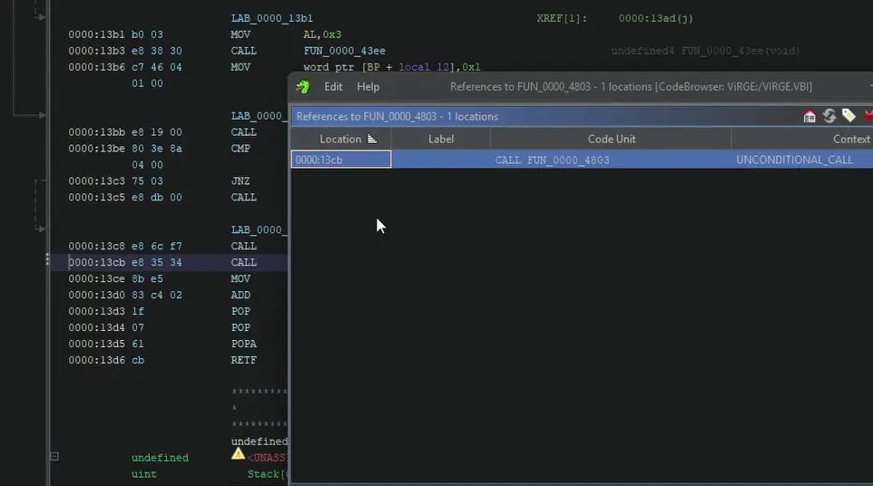
To make the image appear, we have to “hook” into the existing boot process. Using Ghidra, I searched for the string of the original text splash screen to find the function responsible for displaying it.
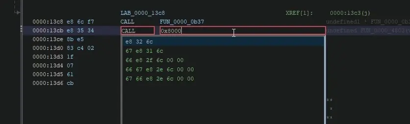
Once I found the call to the text display function (at address 13CB), I patched the instruction to point to my new code at 8000 instead.
The Logic Flow:
- System boots.
- BIOS calls the new “Image Splash” function instead of the existing “Text Splash” function.
- Redirect: Our custom code at
8000runs, loading the palette and drawing the image to the screen. - The Loop: After a 5-second delay, our code calls the original text splash function so the boot process can continue normally.
Phase 4: Fixing the Checksum
A VGA BIOS won’t post if the checksum is wrong. After exporting the modified BIOS from Ghidra, I used my VGA BIOS Checksum Fixer to calculate the new valid byte.
The Result: It Works!
The moment of truth: flipping the power switch. The S3 ViRGE now displays a “crisp” (192×160), 256-color image for 5 seconds before transitioning into the standard VGA text and booting the OS.