If you’ve spent any time with vintage S3 graphics cards – be it the Trio 3D, Trio64, or Virge – you’ve likely noticed a common quirk: the blacks just aren’t black. On a modern LCD or a high-end CRT, the background often appears as a washed-out, dark gray.
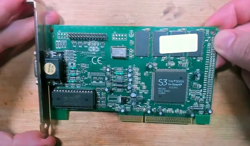
I recently rescued an S3 Trio 3D 2X from a scrapyard and decided it was time to move past the “just turn down your monitor brightness” advice. Instead, I went into the hex code to fix it at the source.
The Mystery of the Gray Background
The “Brightness Bug” isn’t actually a bug; it’s a legacy feature of the NTSC TV standard. In the days of composite video, hardware manufacturers used a “Pedestal” (a 50mV voltage offset) to ensure the TV didn’t confuse the color black with the “blanking pulse” that tells the screen to jump to the next line.
While this helped 1980s television sets stay in sync, it ruins the contrast on VGA monitors. On an S3 card, this is controlled by a single bit: The Pedestal Bit.
Phase 1: Hunting the Bit with DEBUG
Before modifying the BIOS, I had to find where the bit lived in the hardware registers. Using the S3 data sheets as a map, I used the MS-DOS DEBUG application to talk to the chip’s sequencer (Index 3C4h, Data 3C5h).
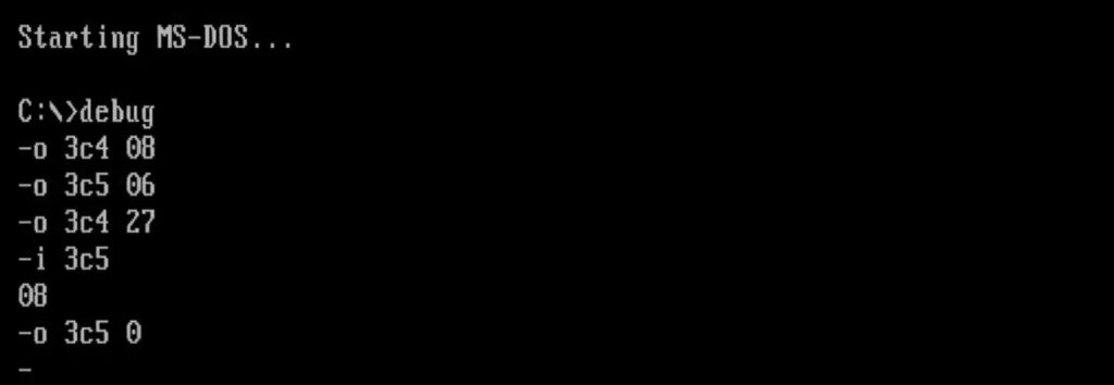
After unlocking the chip with a specific key (06h), I began hunting through the addresses. On this specific Trio 3D 2X, the magic happened at Address 27h.
- Original Value:
08h(Binary00001000) - The Fix: Changing the value to
00htoggled that 4th bit, and the screen instantly snapped from gray to a perfect, deep black.
Phase 2: Permanently Patching the BIOS
Toggling bits in DEBUG is great for testing, but it resets every time you reboot. To make it permanent, we have to modify the VGA BIOS itself.
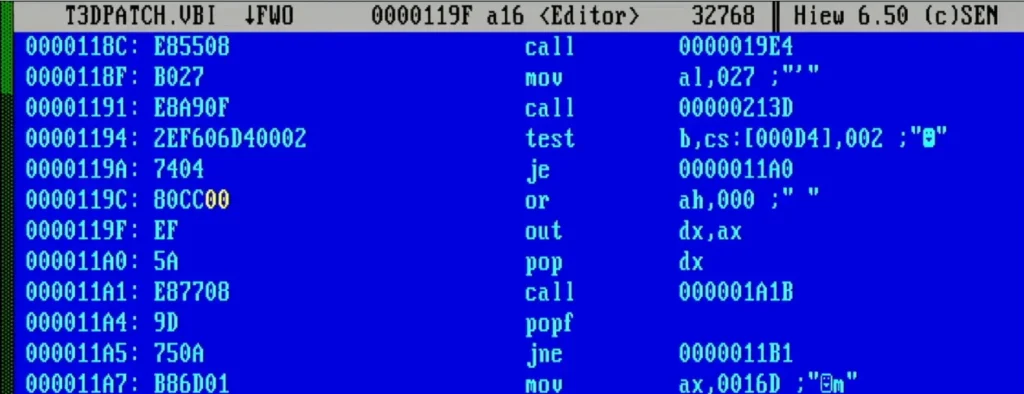
- Dumping the BIOS: I used NSSI to dump the raw
.VBIfile. - Hex Editing with HIEW: I searched for the pattern identified in DEBUG. I looked for the sequence where the code unlocks the chip and writes to Address
27h. - The Modification: I located the byte
08hassociated with the pedestal register and changed it to00h.
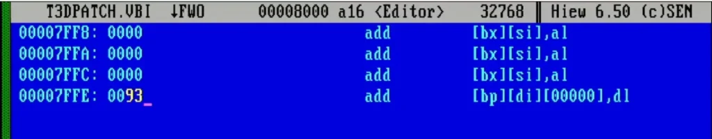
Phase 3: The Checksum Math
A BIOS won’t boot if the checksum is wrong. The system adds every byte in the BIOS together; if the result doesn’t end in 00h, the card is rejected.
Since I reduced my byte value from 08h to 00h (a reduction of 8), I had to compensate by adding 8 to the checksum byte at the end of the file. In my case, I changed the checksum from 8Bh to 93h.
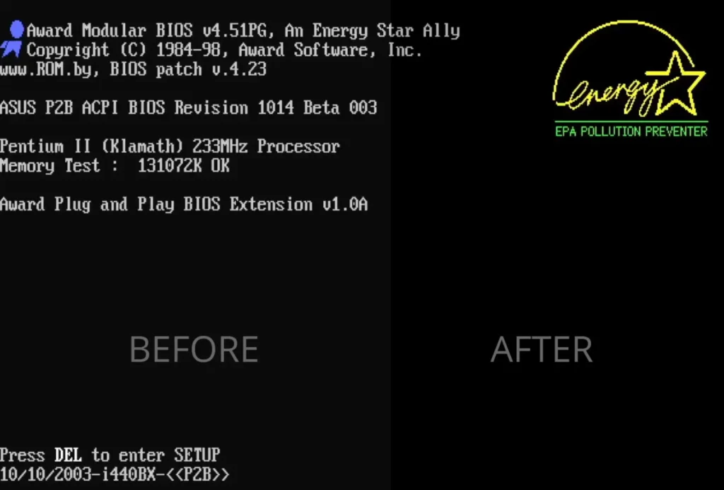
After burning the modified code to a new EPROM chip, the card now boots with perfect black levels immediately from the POST screen. No software drivers or monitor adjustments required.
Download the Patch
You can download my patched BIOS and the original dump below. Note: Use this at your own risk and ensure it matches your specific PCB revision!